


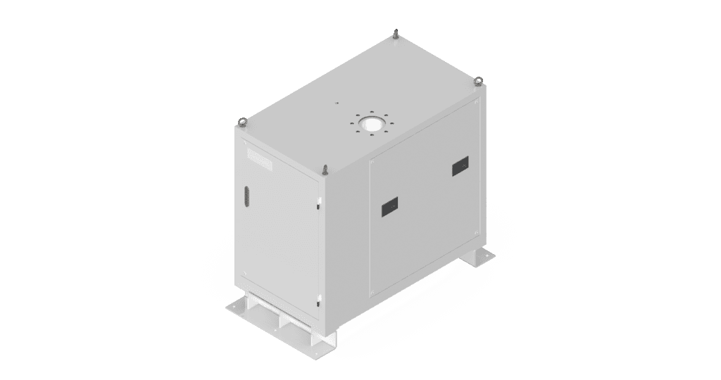
Performance-Optimized Enclosure
The turbo blower enclosure is a protective outer casing engineered to ensure that the performance of the high-speed rotating air compressor and internal electrical components remain uncompromised. At NS, we have leveraged years of research and development, along with cutting-edge technology, to create a turbo blower enclosure that delivers both low loss and low noise performance.
Type
Integrated (standard) / Inlet flange type / Outdoor type / Electrical & inverter split type / Custom type
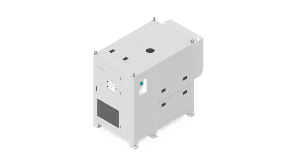
Standard Types

Single core
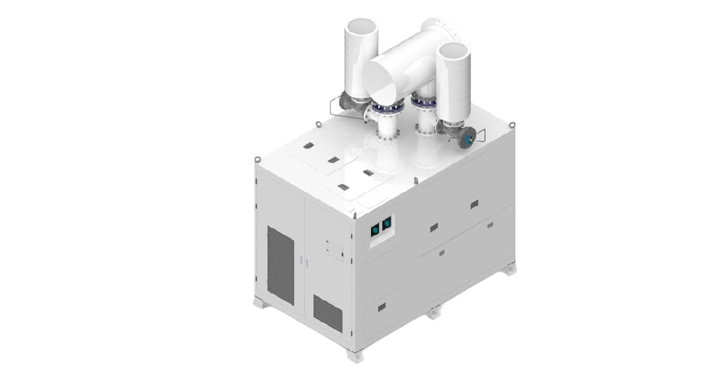
Dual core
Inlet Flange Type
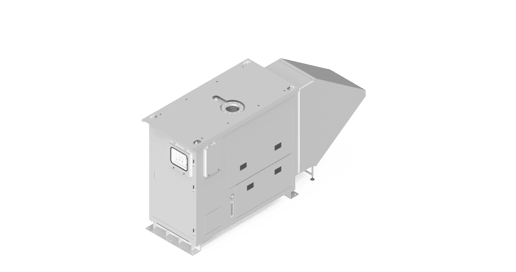
Outdoor Type
Split Type
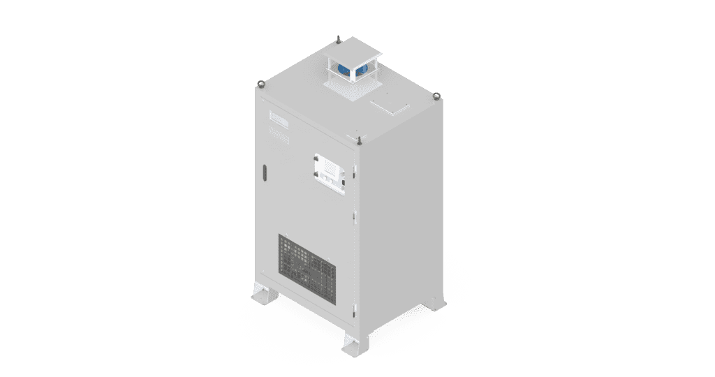
Electrical & inverter section
Core section
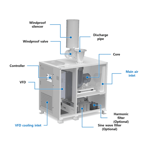
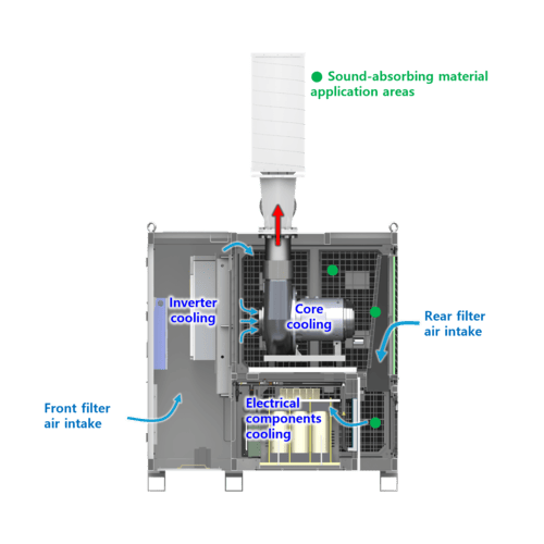
Configuration
Optimized internal airflow and low-noise design
Configuration
Configuration
Automatic Control
PLC
NS products use PLC for control, offering the following advantages:
- Stable control in industrial settings
- Supports various communication protocols for remote operation (Modbus, Profibus, Profinet, Ethernet IP, XGT)
- Supports Analog & Digital I/O for hardwiring type connections
- Easy maintenance
- Real-time monitoring and user-friendly control via HMI
PLC options to meet customer needs
- Allen-Bradley: Compactlogix, Micrologix
- SIEMENS: S7-1200 Series
- LS Electric: XGB, XGT Series
- RS Automation: X8 Series
- Delta: DVP Series
HMI
7-inch wide high-resolution color touchscreen for easy use
Multiple language settings available
- Supported languages: Korean, English, Chinese, Japanese, Russian, Turkish
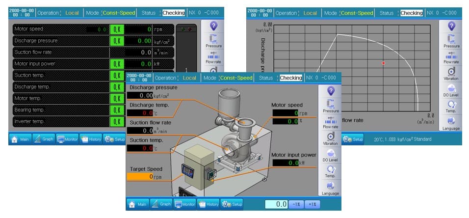
HMI screen configurations
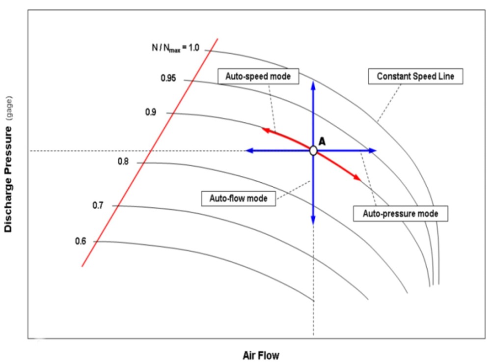
Control Modes
Customers can choose their desired control method:
- Constant Speed Control
- Constant Flow Control
- Constant Pressure Control
- DO Link Control
- Constant Power Control
Master Control Panel (MCP)
A system designed to control multiple blowers or compressors, enabling individual or integrated operation via SCADA and remote communication
- Integrated control of up to 8 blowers
- Supports LAN communication between MCP and blowers
- Supports Modbus RTU, Modbus TCP, Profibus DP communication between MCP and SCADA
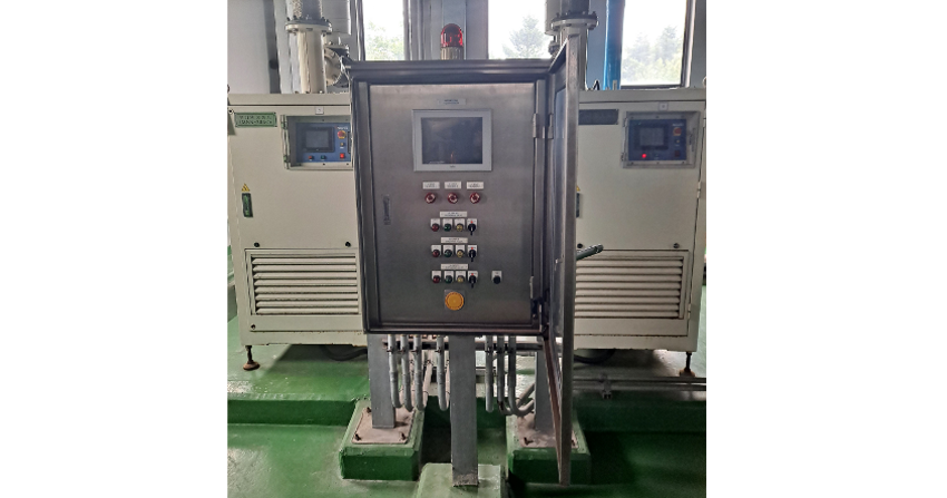
MCP
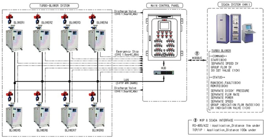
Integrated control diagram
Electrical Filter
Harmonic Filter
Harmonic filters are installed at the power input side to eliminate harmonics generated by equipment. They are designed per IEEE-519 Standard (THD-V < 5%, THD-I < 8%)
Harmonic filters can be installed inside the blower enclosure (no additional space needed), or externally if required
They are equipped with a dedicated breaker to prevent reactive power flow under no-load conditions
Benefits of harmonic filter installation:
- Improves power quality
- Increases transformer and system capacity
- Prevents equipment malfunction due to harmonics
- Provides noise blocking effect for non-linear loads
- Reduces system losses
Harmonic Filter

External installation type
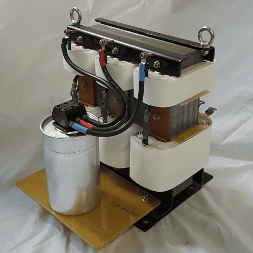
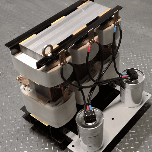
Sine Wave Filter
Sine wave filters convert the inverter’s PWM waveform to a sine wave and are installed on the motor input side to protect the motor
NS sine wave filters are designed to operate at motor speeds up to 60,000 RPM
Benefits of sine wave filter installation:
- By applying a sine wave input to the motor, heat generation is reduced and insulation breakdown is prevented.
- Reduced motor noise and electromagnetic interference
- Improved motor efficiency
- Extended motor lifespan
- Enables long-distance transmission of inverter output, allowing the motor and inverter to be installed separately in different locations
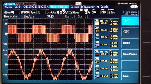
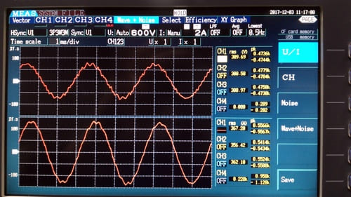
Sine wave filter effect
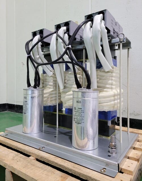
Sine Wave Filter